The Renderer
The nice surprise
It turns out that the Windows Direct2D API rasterizes any fillable graphics paths, like glyph contours, perfectly and easily, down to the tiniest size of the glyphs - thank you very much !!!
See, I am perfectly comfortable with a "3rd" party implementation of something like this, as opposed to writing it myself, IF and ONLY if the "3rd party" is the operating system - where, afterall, such capability should exist.
Thus, the Renderer was born. Not only would it become a separate COM object because I could see it's value for more than just font rendering, or, for that matter, other PostScript graphics operations, but it was clear that ANY problem domain needing graphics could take advantage of it.
In keeping with my insistence on a solid software integration architecture, all graphics operations were removed from the PostScript project AND the Font Manager project and placed here, not only because it's so convenient, but because doing so is a huge help in fleshing out it's functionality and finding and removing bugs.
The easiest way to describe how to use this object is to describe its interfaces. Note that this grew out of the work implementing my PostScript interpreter. Therefore, you may recognize PostScript drawing sequences in these interfaces. Those drawing commands are relatively straightforward and work well, so I kept them in place and all clients would essentially end up using the PostScript graphics syntax.
First, there are three basic areas (interfaces) implemented in Renderer:
- Renderer
The "controlling" interface. Configuration, for example, provide any transformation matrices, the device context, etc.
- Graphic Elements
The drawing commands, like move to, line to, image, etc.
- Graphic Parameters
Characteristics such as line color, fill color, line style, etc.
The three areas use these published interfaces.
IRenderer
      interface IRenderer {

        HRESULT put_TransformMatrix(UINT_PTR /*XFORM*/ pXformToDeviceSpace);
        HRESULT put_DownScale(FLOAT downScale);
        HRESULT put_Origin(POINTF origin);

        HRESULT Render(HDC hdc,RECT *pDrawingRect);
        HRESULT Discard();
        HRESULT ClearRect(HDC hdc,RECT *pRect,COLORREF theColor);

    };
Some notes:
put_TransformationMatrix
specifies the XFORM that will convert any graphics element coordinates into the current device space. That is into the coordinate space active for the device context you'll pass when calling Render. Note further that the coordinate system of your input graphic elements (next interface) are of no concern to the Renderer. The transform you pass here contains all the information to convert whatever they are, into the device space.
Note the syntax "put_Value" is useful for some late-binding languages. For example, in Visual Basic, this method is invoked by:
object.TransformationMatrix = value
put_DownScale
This specifies a scaling value that actually scales down the coordinates as the content is rendered.
You may not always need this, however, after a whole lot of angst trying to figure out why I was getting horrible visual performance in rasterization at small sizes. I finally realized that it was necessary to scale UP the coordinates before sending them to the renderer, and then to have the renderer scale them back down when the graphics primitives are drawn. I have to assume that the graphics primitives are losing precision when the coordinates are small, because the Windows Direct2D uses FLOATs for coordinates (?!?!) - for some insane reason instead of doubles!
If you are getting poor rasterization results at small sizes, try scaling the coordinate values (in your code) before sending them to the renderer (IGraphicElements). Don't forget to call DownScale before you send those IGraphicElements. To summarize, pass a value to this method, perhaps 64.0f. Then, scale the coordinates of your graphics primitives (in your code), in both the x and y directions up by that amount before adding them to the graphics page (like the x and y in LineTo). You don't need to do anything else, the Renderer will "downscale" the coordinates before rendering the elements.
put_Origin
specifies a "dynamic" origin as the reference point for any primitives (moveto, lineto, etc) that you subsequently provide.
A perfect example is the drawing of font glyphs. Glyphs are defined in a coordinate system specific to that glyph. For example, each glyph has it's own "box", and all coordinates in the contours are relative to that box. The origin of the box itself is never specified. Therefore, for consequetive glyphs, you could, for example, set the "origin" for drawing the second glyph as the "endpoint" of the first glyph, at least in the "x" direction, and you then don't have translate each glyph into one global (or page if you will) coordinate system.
Render
actually show the graphics on the given device context in the specified RECT (in device coordinates (pixels)). Note that the device context can be that of a window, a bitmap, or printer, the Renderer doesn't care.
Note also that the Renderer does not actually draw the graphics while you are sending them. It only draws them when you call Render.
I hope you notice the stunning speed with which those graphics actually appear. Even the page of a highly complex document represented in PostScript will literally "pop" onto the window, it is amazing.
Discard
Discards the current primitives buffer. Maybe it was drawn by mistake.
ClearRect
Sets the background of the rendered device context. For example, if you are drawing to a bitmap, if you don't set the color, it will be black. In the case of a window device context, that color may depend on what painting operation happens on it's owning window.
There are some other methods in the IRenderer interface, but their usage is relatively obvious, and I want to move on to IGraphicElements.
A very good reference for using the IRenderer interface is here. This is also an excellent reference of how the Font Manager composes the glyph geometries from the font's binary data. You'll also see that drawing each glyph does not actually result in it appearing at the time. Instead, the PostScript Interpreter draws all graphics accumulated, by calling Render, when the entire page should be shown. This is not only lightning fast to show the page, it is keeping with the PostScript language, graphics are not shown until the ps showpage operator is called.
IGraphicElements
    interface IGraphicElements  {

        HRESULT NewPath();
        HRESULT ClosePath();
        HRESULT StrokePath();
        HRESULT FillPath();

        HRESULT MoveTo(FLOAT x,FLOAT y);
        HRESULT MoveToRelative(FLOAT x,FLOAT y);

        HRESULT LineTo(FLOAT x,FLOAT y);
        HRESULT LineToRelative(FLOAT x,FLOAT y);

        HRESULT Arc(FLOAT xCenter,FLOAT yCenter,FLOAT radius,FLOAT startAngle,FLOAT endAngle);
        HRESULT Ellipse(FLOAT xCenter,FLOAT yCenter,FLOAT xRadius,FLOAT yRadius);
        HRESULT Circle(FLOAT xCenter,FLOAT yCenter,FLOAT radius);
        HRESULT CubicBezier(FLOAT x0,FLOAT y0,FLOAT x1,FLOAT y1,FLOAT x2,FLOAT y2,FLOAT x3,FLOAT y3);

        [helpstring("Call move to before your first QuadraticBezier in a chain to set the startpoint")]
        HRESULT QuadraticBezier(FLOAT x1,FLOAT y1,FLOAT x2,FLOAT y2);

        HRESULT Image(HDC hdc,HBITMAP hBitmap,UINT_PTR /*xForm*/ pPSCurrentCTM,FLOAT width,FLOAT height);

        [helpstring("Pass 0.0 for width or height to display in native bitmap width.")]
        HRESULT NonPostScriptImage(HDC hdc,HBITMAP hBitmap,FLOAT x0,FLOAT y0,FLOAT displayWidth,FLOAT displayHeight);

    };
Through the above interface, you specify what is drawn and where.
If not familiar with "paths", note that it is a prevalent concept in PostScript, and in Windows GDI for that matter.
In general, a path is the connected set of lines that formulate some kind of line drawing. Or, the lines that define the contour (edges) in a filled region, such as a font glyph. If you want to draw lines, you should first call NewPath, then call MoveTo to set the first coordinate in that line "path", followed by LineTo(s) to create the line segments.
When your path construction is complete, you call either StrokePath, ClosePath, or FillPath:
- StrokePath: draws the line from the initial point, through all "LineTo" points and ends at the last lineto point
- ClosePath: draws the line from the initial point, through all "LineTo" points, then again to the initial point.
- FillPath: does an implicit ClosePath, that is the last point is the first point. Then it fills that geometry with the current background color
- If you do not call one of these before a MoveTo, then the system will create an implied ClosePath followed by NewPath with that starting point
The other methods in this interface cause the appropriate graphics item to be emitted on the device context (after you call Render)
IGraphicParameters
    interface IGraphicParameters {

        HRESULT SaveState();
        HRESULT RestoreState();

        HRESULT put_LineWidth(FLOAT lw);
        HRESULT put_LineJoin(long lj);
        HRESULT put_LineCap(long lc);
        HRESULT put_LineDash(FLOAT *pValues,long countValues,FLOAT offset);

        HRESULT put:RGBColor(COLORREF rgb);

    };
This interface sets the "characteristics" of the graphics elements that are subsequently created by calls in the IGraphicElements interface
Their usage is pretty obvious except for SaveState, and RestoreState.
Those two methods allow you to override the current settings a) without necessarily knowing what they are, and b) so that they can be completely restored after you've issued the graphic elements that use the new (temporary) settings.
You can SaveState/RestoreState to any depth.
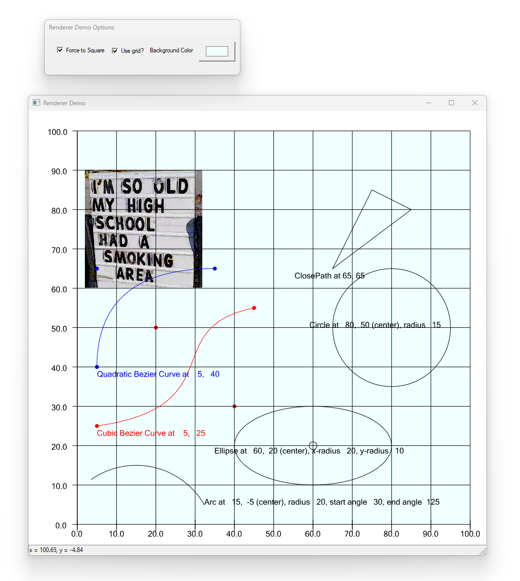
The Renderer Demo application
I've built a simple demo project to show how easy it is to use this component to put graphics in your own system.
The demo is a windows application that hosts this project as a COM component and creates each of the typical graphics primitives in a clean and robust way. You can see immediately how easy, and flexible, this component really is for rendering graphics, which includes all manner of text, right away (the demo also shows the use of the [Font Manager](../EnVisioNateSW_FontManager/Readme.md) object).
The repository for the demo is here.. It was so much fun to build and show off the demo, I've created a whole separate page here for it on the website too.
Please check out the power and ease of the EnVisioNateSW Renderer by taking a look at this demo.